Product Description
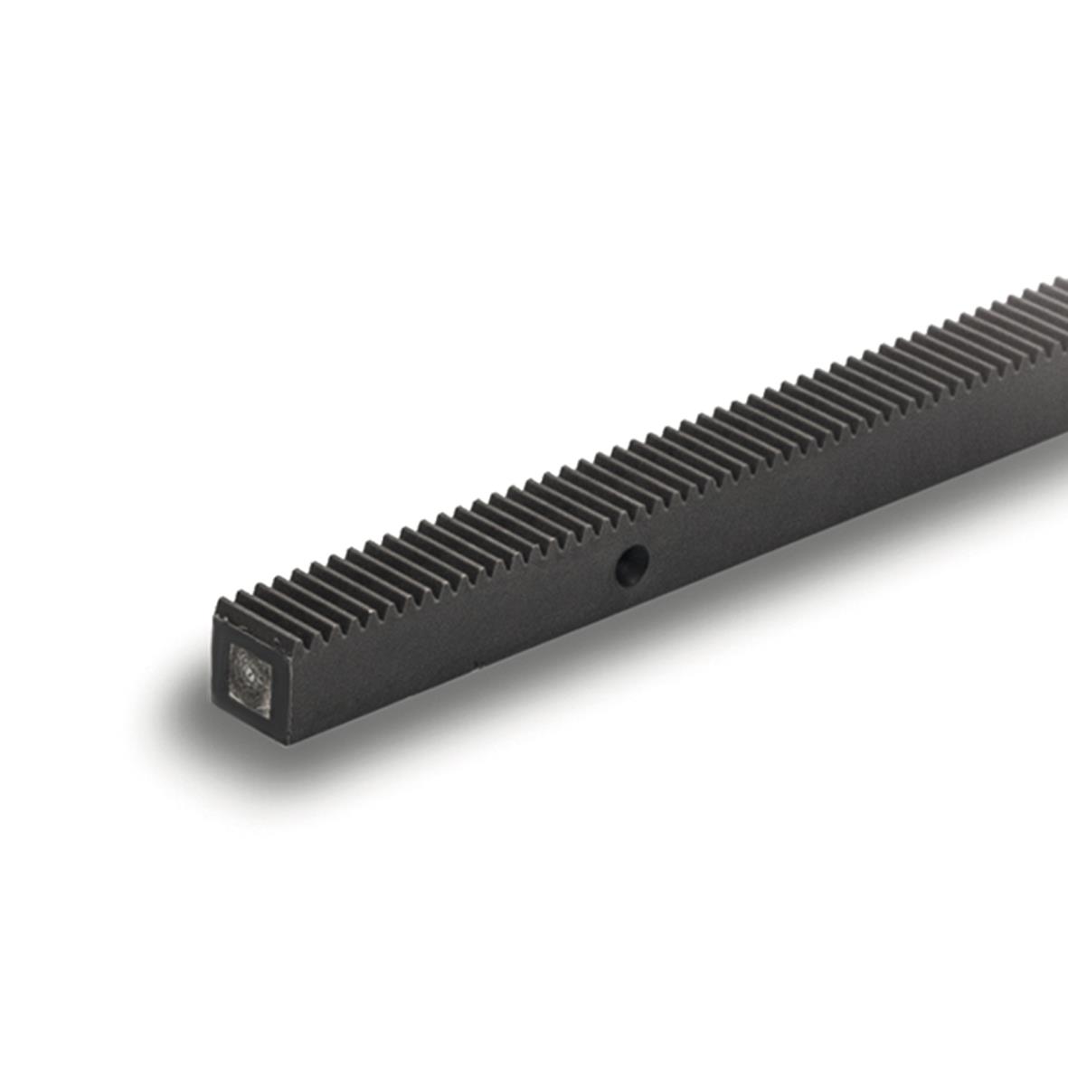
High Precision Gear Rack and Pinion for Construction Hoist Use Construction Spare Parts
Product Description
| Material | Steel 45# | Shape | Rack |
| Scope of application | SC200 SC100 | Tooth height | 60mm |
| Number of teeth | M8-1508 | Tooth width | 8MM |
| Tooth line shape | Spur gear | weight | 24KG |
Certifications
Packaging & Shipping
FAQ
High Precision Gear Rack and Pinion for Construction Hoist Use Construction Spare Parts
1. What are your main products?
We produce Construction Hoist (also called construction elevator, construction lift) and spare parts of it.
2. Are all Construction Hoist the same from all Vendors & Manufacturers?
Our High rise building construction hoist with VFD for lifting materials and passengers have exported to Europe, Middle and southern America, most of Asia, and some countries from Africa, about 50 countries. We can well match European standards, Russia standards and America standards. We have technology for develope new design ability and we support many customer with good solutions to solve their construction site special vertical access problems.
3. Do your products have some certificates?
Yes. Our Construction Hoist have passed CE ,ISO Certificates.
4. What are the payment terms and the delivery time?
Payment terms are T/T and LC. We will ship the cargo within 20-30 days after receiving the 30% deposit.
5. Are you manufacturer or the trader?
We are manufacturer with 14 years maker experiences, have advanced production line and inspection device. Our Research and development team have got many praise from customers.
6. Will you develop distributor and sole agent?
Yes, should you have any interest to be our distributor and agent, please let us know in any ways. Sole agent is available depend on the sales turnover.
7. Where do you ship to and what countries have you done business in?
We provide quick and efficient shipping to countries all over the world from HangZhou port or other China port.
We have done business with customers in many countries, such as Mexico, Brazil, Korea, Malaysia, Thailand, India, Vietnam, Indonesia, UAE, Qatar, Kuwait,Saudi Arabia etc.
We will provide best price once confirmed the above. You can get our feedback within 12 hours !
/* January 22, 2571 19:08:37 */!function(){function s(e,r){var a,o={};try{e&&e.split(“,”).forEach(function(e,t){e&&(a=e.match(/(.*?):(.*)$/))&&1
| After-sales Service: | Online Service |
|---|---|
| Warranty: | 1 Year |
| Type: | Bucket Teeth |
| Application: | Hoisting Machinery |
| Certification: | CE, ISO9001: 2000 |
| Condition: | New |
| Samples: |
US$ 20/Piece
1 Piece(Min.Order) | |
|---|
| Customization: |
Available
| Customized Request |
|---|
What safety considerations should be kept in mind when working with rack and pinion?
Working with rack and pinion systems requires careful attention to safety to prevent accidents and ensure the well-being of individuals involved. Here are some important safety considerations to keep in mind when working with rack and pinion:
- Proper Guarding: Ensure that the rack and pinion system is properly guarded to prevent accidental contact with moving parts. Install appropriate barriers, shields, or enclosures to restrict access to the rack and pinion assembly, especially in areas where there is a risk of entanglement or pinch points.
- Lockout/Tagout: Implement lockout/tagout procedures when performing maintenance, repair, or adjustment on the rack and pinion system. Lockout/tagout procedures involve isolating the power source and securing it with a lock or tag to prevent accidental energization or motion during work, protecting workers from unexpected movement or startup.
- Proper Installation: Ensure that the rack and pinion system is installed correctly according to manufacturer guidelines and industry standards. Improper installation can lead to misalignment, instability, or premature failure, posing safety risks. Follow proper procedures for mounting, alignment, and securing of the rack and pinion assembly.
- Maintenance and Inspection: Regularly inspect and maintain the rack and pinion system to ensure its proper functioning and identify any potential safety hazards. Check for signs of wear, damage, or loose components. Lubricate the system as recommended by the manufacturer to maintain smooth operation and prevent excessive friction or overheating.
- Load Limitations: Adhere to the load limitations specified by the manufacturer. Overloading the rack and pinion system can lead to excessive stress, premature wear, or failure, potentially resulting in accidents. Consider factors such as weight, distribution, and dynamic forces when determining the appropriate load for the system.
- Training and Awareness: Provide adequate training to personnel who will be working with or around the rack and pinion system. Ensure they understand the potential hazards, safe operating procedures, and emergency protocols. Promote awareness of the risks associated with the system and encourage a safety-conscious culture in the workplace.
- Environmental Considerations: Take into account the environmental conditions in which the rack and pinion system operates. Factors such as temperature, humidity, corrosion, or exposure to hazardous substances may affect the system’s performance and safety. Use appropriate materials, coatings, or protective measures to mitigate potential risks.
- Emergency Stop: Install an emergency stop mechanism that allows for immediate shutdown of the rack and pinion system in case of emergencies or hazardous situations. Clearly mark and communicate the location of the emergency stop controls to ensure quick and easy access when needed.
It is essential to consult the manufacturer’s documentation, safety guidelines, and applicable regulations when working with rack and pinion systems. By following proper safety practices, implementing appropriate safeguards, and promoting a safety-focused mindset, the risks associated with working with rack and pinion systems can be minimized, creating a safer working environment.
How do rack and pinion systems contribute to precise motion control?
Rack and pinion systems play a crucial role in achieving precise motion control in various applications. The inherent design and characteristics of rack and pinion mechanisms contribute to their ability to provide accurate and reliable motion control. Here’s a detailed explanation:
1. Direct and Efficient Power Transmission: Rack and pinion systems offer direct power transmission, meaning there are no intermediate components or linkages between the input and output. This direct connection allows for efficient power transfer without significant energy losses. As a result, the motion control system can respond quickly and accurately to input commands, enabling precise control over the position, speed, and acceleration of the driven load.
2. High Mechanical Advantage: Rack and pinion systems provide a mechanical advantage, especially in applications where linear force or torque needs to be converted. The gear ratio of the system determines the mechanical advantage, allowing for amplification or reduction of the input force or torque. By adjusting the gear ratio, the system can be optimized to achieve the desired level of precision and force transmission. The mechanical advantage enhances the system’s ability to overcome friction, resist external disturbances, and maintain positional accuracy.
3. Minimal Backlash: Backlash refers to the slight clearance or play between the teeth of the gears in a mechanical system. Rack and pinion systems are designed to minimize backlash, ensuring precise and repeatable motion control. The tight engagement of the gear teeth in a rack and pinion mechanism reduces backlash, resulting in minimal lost motion and improved accuracy. This characteristic is particularly important in applications that require precise positioning, such as CNC machines, robotics, or optical equipment.
4. Smooth and Continuous Motion: Rack and pinion systems can provide smooth and continuous motion due to the constant contact between the gear teeth. The teeth on the pinion gear mesh with the teeth along the rack’s length, resulting in a continuous transfer of motion. This continuous contact helps to eliminate jerks, vibrations, or hysteresis that could affect the precision of the motion control system. The smooth and continuous motion is vital for applications where precise speed control or smooth trajectory tracking is required.
5. High Positional Accuracy: Rack and pinion systems excel at achieving high positional accuracy. The linear nature of the motion provided by the rack allows for precise control over the position of the driven load. Combined with low backlash, the system can accurately maintain the desired position without significant deviation. This level of positional accuracy is critical in applications such as CNC machining, 3D printing, or metrology, where tight tolerances and precise positioning are essential.
6. Scalability and Flexibility: Rack and pinion systems offer scalability and flexibility, making them suitable for a wide range of applications. They can be designed and implemented in various sizes and configurations to accommodate different load capacities, travel distances, and speed requirements. The modular nature of rack and pinion systems allows for easy integration into different mechanical systems, making them adaptable to diverse motion control applications.
In conclusion, rack and pinion systems contribute to precise motion control through their direct power transmission, high mechanical advantage, minimal backlash, smooth and continuous motion, high positional accuracy, and scalability. These characteristics make rack and pinion mechanisms a popular choice in numerous industries, including robotics, automation, manufacturing, and automotive, where precise and reliable motion control is vital.
In which industries are rack and pinion systems commonly used?
Rack and pinion systems find extensive use in various industries where precise linear motion is required. These mechanisms are valued for their efficiency, reliability, and ability to convert rotational motion into linear motion. Here’s a detailed explanation of the industries in which rack and pinion systems are commonly used:
- Automotive Industry: Rack and pinion systems are widely employed in the automotive industry for steering systems. They are used in passenger cars, commercial vehicles, and other automotive applications to provide smooth and responsive steering control.
- Machinery and Manufacturing: Rack and pinion systems are commonly found in machinery and manufacturing applications. They are utilized in CNC machines, industrial automation systems, packaging machinery, material handling equipment, and assembly line systems to enable precise linear motion for various processes.
- Robotics and Automation: Rack and pinion systems play a crucial role in the robotics and automation industry. They are used in robotic arms, manipulators, joint mechanisms, and linear actuators to provide controlled linear motion for tasks such as lifting, extending, and positioning.
- Construction and Infrastructure: Rack and pinion systems are utilized in the construction and infrastructure sectors. They are commonly found in construction machinery like cranes and lifts, enabling vertical movement and precise positioning of heavy loads.
- Entertainment and Stage: Rack and pinion systems are widely used in the entertainment industry, particularly in stage and theater equipment. They are employed in moving platforms, scenery automation, and lifting mechanisms to facilitate controlled and smooth movement during performances.
- Printing and Packaging: Rack and pinion systems are commonly utilized in the printing and packaging industry. They are found in digital printers, large-format plotters, and packaging machinery, providing the necessary linear motion for accurate printing and packaging processes.
- Transportation and Logistics: Rack and pinion systems are employed in transportation and logistics applications. They are used in elevators, escalators, and material handling systems, enabling vertical movement, efficient transportation, and precise positioning of goods and people.
- Medical and Healthcare: Rack and pinion systems find application in the medical and healthcare industry. They are used in medical devices, hospital equipment, and diagnostic machinery, providing controlled linear motion for tasks such as patient positioning and sample handling.
- Agriculture and Farming: Rack and pinion systems are utilized in the agriculture and farming sector. They can be found in agricultural machinery like harvesters and sprayers, facilitating controlled linear motion for various farming processes.
These are just a few examples of industries where rack and pinion systems are commonly used. Their versatility, precision, and reliability make them suitable for a wide range of applications that require linear motion conversion.


editor by Dream 2024-05-16
China supplier CNC Machining Forged Steel Precision Spur Rack and Pinion Railway worm gearbox
Product Description
Key attributes
Other attributes
Applicable Industries
Manufacturing Plant, Construction works , Energy & Mining
Weight (KG)
3000
Showroom Location
None
Video outgoing-inspection
Provided
Machinery Test Report
Provided
Marketing Type
Ordinary Product
Warranty of core components
Not Available
Core Components
Gear, Ring Gear
Place of CHINAMFG
ZheJiang , China
Condition
New
Warranty
1year
Shape
Ring Gear
Standard or Nonstandard
Nonstandard
Tooth Profile
Helical Gear,spur gear
Material
Steel
Processing
Forging
Pressure Angle
custom
Brand Name
TS
Product Name
Large Ring Gear
Module No.
5-180
Process
Milling,hobbing
Surface treatment
as request
Heat treatment
Q&T
Application
Industry machinery,transmission equipment
Standard
DIN ANSI ISO
Certificate
ISO
OEM Service
YES
Delivery time
15-60days
Packaging and delivery
Packaging Details
Package adapting to CHINAMFG transport
Port
ZheJiang ,HangZhou
Supply Ability
Supply Ability
5 Piece/Pieces per Month
OUR WORKSHOPS
OUR EQUIPMENTS
Technology Process
|
Material |
Carbon steel,Alloy steel |
||
|
Structure |
Forging,casting |
||
|
Type of gear |
spur gear,helical gear,Planetary Gear |
||
|
Heat treatment |
Quenching and tempering |
||
|
Process |
forging, rough machining, QT, finish machining |
||
|
Main equipments |
hobbing,CNC machine |
||
|
Module |
up to 200 |
||
|
Precision of gear |
Grinding ISO Grade 5-7 & Hobbing ISO Grade 8-9 |
||
|
Inspection |
Raw material inspection, UT,physical property test,dimension inspect |
||
|
Application |
Mining machinery, mill, kiln and other equipment |
||
OUR CERTIFICATE
OUR CUSTOMER FEEDBACK
CONTACT
/* January 22, 2571 19:08:37 */!function(){function s(e,r){var a,o={};try{e&&e.split(“,”).forEach(function(e,t){e&&(a=e.match(/(.*?):(.*)$/))&&1
| Application: | Industry |
|---|---|
| Hardness: | Hb190-Hb300 |
| Gear Position: | External Gear |
| Samples: |
US$ 100/Piece
1 Piece(Min.Order) | Order Sample |
|---|
| Customization: |
Available
| Customized Request |
|---|
.shipping-cost-tm .tm-status-off{background: none;padding:0;color: #1470cc}
| Shipping Cost:
Estimated freight per unit. |
about shipping cost and estimated delivery time. |
|---|
| Payment Method: |
|
|---|---|
|
Initial Payment Full Payment |
| Currency: | US$ |
|---|
| Return&refunds: | You can apply for a refund up to 30 days after receipt of the products. |
|---|
How do rack and pinion systems handle different gear ratios?
Rack and pinion systems can accommodate different gear ratios by adjusting the size and number of teeth on the gears. The gear ratio determines the relationship between the rotational motion of the pinion gear and the linear motion of the rack. Here’s a detailed explanation of how rack and pinion systems handle different gear ratios:
In a rack and pinion system, the pinion gear is a small gear with teeth that meshes with the rack, which is a long, straight bar with teeth along its length. As the pinion gear rotates, it translates rotational motion into linear motion along the rack. The gear ratio is defined as the ratio of the number of teeth on the pinion gear to the number of teeth on the rack. It determines how much linear motion the rack will produce for each revolution of the pinion gear.
To handle different gear ratios, the following approaches can be taken:
- Varying the Number of Teeth: By changing the number of teeth on the pinion gear and the rack, different gear ratios can be achieved. Increasing the number of teeth on the pinion gear relative to the rack will result in a higher gear ratio, providing more linear motion per revolution of the pinion gear. Conversely, reducing the number of teeth on the pinion gear relative to the rack will yield a lower gear ratio, producing less linear motion per revolution of the pinion gear.
- Modifying the Module and Pitch: The module and pitch of the gear teeth can also be adjusted to accommodate different gear ratios. The module refers to the size of the teeth, while the pitch determines the spacing between the teeth. Changing the module and pitch can alter the gear ratio without significantly affecting the overall dimensions of the rack and pinion system. This approach allows for more flexibility in achieving specific gear ratios while maintaining compatibility with existing system components.
- Using Gear Reduction or Multi-Stage Systems: In certain applications where a wide range of gear ratios is required, gear reduction or multi-stage systems can be employed. Gear reduction involves incorporating additional gears between the pinion and the rack to achieve the desired gear ratio. Each additional gear stage introduces its own gear ratio, allowing for more precise control over the system’s overall gear ratio. This approach is commonly used in applications that require high precision or a wide range of motion control options.
The selection of a specific gear ratio depends on the application requirements, such as the desired linear speed, torque, or positional accuracy. The gear ratio determines the system’s speed and force transmission characteristics, as well as its ability to handle different loads. It is important to note that changing the gear ratio can affect other system parameters, such as backlash, efficiency, and system dynamics. Therefore, careful consideration and analysis of the application’s needs and trade-offs are necessary when selecting and adjusting the gear ratio in a rack and pinion system.
How do rack and pinion systems handle variations in temperature and humidity?
Rack and pinion systems are designed to handle variations in temperature and humidity, ensuring their proper functioning and longevity in diverse environmental conditions. Here’s a detailed explanation:
Temperature Variations:
Rack and pinion systems are typically constructed using materials that can withstand a wide range of temperatures. Some common materials used for rack and pinion components include steel, stainless steel, aluminum, and various engineering plastics. These materials are chosen for their thermal stability and resistance to expansion or contraction due to temperature changes.
When exposed to temperature variations, rack and pinion systems can experience dimensional changes. However, the materials used are selected to minimize the effects of thermal expansion or contraction. Manufacturers consider the coefficient of thermal expansion of the materials and design the system with appropriate tolerances to accommodate temperature-related dimensional changes. This helps maintain the system’s accuracy and functionality over a range of operating temperatures.
In extreme temperature conditions, lubrication becomes an important consideration. High temperatures can cause lubricants to degrade, leading to increased friction and wear. To address this, specialized lubricants that can withstand elevated temperatures are used in rack and pinion systems operating in high-temperature environments. Additionally, regular maintenance and lubrication checks are recommended to ensure optimal performance and to mitigate any adverse effects of temperature variations.
Humidity and Moisture:
Humidity and moisture can affect the performance and durability of rack and pinion systems, particularly if the system is exposed to excessive moisture or operates in highly humid environments. Here are some measures taken to address these challenges:
1. Material Selection: The materials used in rack and pinion systems are often chosen for their resistance to corrosion and moisture absorption. Stainless steel, for example, is commonly used due to its excellent corrosion resistance. Similarly, certain types of engineering plastics are less susceptible to moisture absorption, making them suitable for humid environments.
2. Protective Coatings: Applying protective coatings on rack and pinion components can help enhance their resistance to moisture and corrosion. Coatings such as zinc plating, chrome plating, or specialized corrosion-resistant coatings provide an additional barrier against moisture penetration and prolong the system’s lifespan.
3. Sealing and Gasketing: Rack and pinion systems can be designed with sealing mechanisms or gaskets to prevent moisture ingress. Seals and gaskets are placed at critical points, such as the gear meshing area or the housing joints, to create a barrier against moisture and contaminants. These seals help maintain the integrity of the system, reduce the risk of corrosion, and ensure consistent performance even in humid conditions.
4. Regular Maintenance: Regular maintenance practices, including cleaning, inspection, and lubrication, are essential for rack and pinion systems exposed to humidity. Cleaning the system to remove any accumulated dirt or moisture, inspecting for signs of corrosion or wear, and applying appropriate lubrication can help mitigate the effects of moisture and ensure the system’s optimal performance and longevity.
By incorporating suitable materials, protective coatings, sealing mechanisms, and maintenance practices, rack and pinion systems can effectively handle variations in temperature and humidity. These measures help maintain the system’s accuracy, reliability, and durability, even in challenging environmental conditions.
What are the key components of a rack and pinion mechanism?
A rack and pinion mechanism consists of several key components that work together to convert rotational motion into linear motion. Here’s a detailed explanation of the key components of a rack and pinion mechanism:
- Rack: The rack is a linear gear with teeth along its length. It is a long, straight bar that serves as the linear motion component of the mechanism. The rack is often made of metal or plastic and is designed with precision to ensure smooth engagement with the pinion.
- Pinion: The pinion is a small gear with teeth that mesh with the teeth on the rack. It is the rotational motion component of the mechanism. The pinion is typically mounted on a shaft and is connected to a rotary motion source, such as an electric motor or a manual crank.
- Teeth: The teeth on both the rack and the pinion are integral to the mechanism’s operation. The teeth of the pinion mesh with the teeth on the rack, allowing for the transfer of motion. The tooth profile and spacing are crucial for ensuring smooth and efficient engagement between the rack and pinion.
- Bearing Support: To ensure smooth and reliable operation, a rack and pinion mechanism often incorporates bearing support. Bearings are used to support the pinion shaft, reducing friction and allowing for smooth rotation. Bearings may also be used to support the rack, depending on the specific design and application.
- Guides: Guides are used to guide and support the linear motion of the rack. They help maintain alignment and prevent lateral movement or misalignment during operation. Guides can be in the form of rails, tracks, or other structures that keep the rack in the desired path of motion.
- Housing or Mounting Structure: A rack and pinion mechanism may include a housing or mounting structure to provide support, stability, and proper alignment of the components. The housing or structure ensures that the rack and pinion remain securely in place, maintaining the integrity of the mechanism during operation.
- Additional Components: Depending on the specific application, a rack and pinion mechanism may incorporate additional components. These can include lubrication systems to reduce friction and wear, position sensors for feedback and control, and protective covers or enclosures to shield the mechanism from dust, debris, or environmental elements.
Each of these components plays a vital role in the operation of a rack and pinion mechanism, enabling the conversion of rotational motion to linear motion with precision and efficiency.
editor by Dream 2024-05-16
China Professional Rhd Power Steering Rack Gear and Pinion 6q2423055j-a 6q2423055r gear ratio calculator
Product Description
Products Description
|
Product Name |
Power Steering Gear Assembly |
|||
|
Condition |
New |
|||
|
Material |
Aluminum |
|||
|
Quality |
100% Test |
|||
|
Part Number |
6Q2423055J-A 6Q2423055R |
|||
Details Images
Our Advantages-Why Choose Us
Transport
FAQ
Q: Are you trading company or manufacturer ?
A: We are the set design, development, production, sale and service of industry and trade-oriented enterprises.
Q: What is the MOQ?
A: MOQ depends on our clients demands, we welcome trial order before mass production.
Q: How does your factory make sure the product quality?
A: Durning production, we have FQC, IQC ,IPQC and OQC to control the quality. We will final check before shipping to avoid any problem.
Q: What is your terms of payment ?
A: T/T, paypal, ali-pay,west union, cash, etc, paid before shippment.
Q:What is the warranty?
A:One year for CHINAMFG parts and 3 years for OEM parts.
Q:Can you send products to my country?
A:Sure,we can. We can ship the goods by express or by sea.
Q:Can you do OEM for me?
A: We accept OEM and ODM.
Q: How can I place the order?
A: Confirm PI or Invoice, make payment, then we will arrange shipment soon.
Q: When can I get the quotation ?
A: We usually quote you within 24 hours after we get your inquiry. If you are very urgent to get the quotation.Please call us or tell us in your mail, so that we could regard your inquiry priority.
/* January 22, 2571 19:08:37 */!function(){function s(e,r){var a,o={};try{e&&e.split(“,”).forEach(function(e,t){e&&(a=e.match(/(.*?):(.*)$/))&&1
| After-sales Service: | 12 Months |
|---|---|
| Warranty: | 12 Months, 1 Year |
| Type: | Steering Gears/Shaft, Steering Gear |
| Material: | Aluminum, Aluminum |
| Certification: | ISO, CE |
| Automatic: | Automatic |
| Customization: |
Available
| Customized Request |
|---|
Can rack and pinion systems withstand variations in environmental conditions?
Rack and pinion systems are designed to operate effectively in a wide range of environmental conditions. However, the ability of a rack and pinion system to withstand variations in environmental conditions depends on several factors, including the materials used, the design of the system, and the specific conditions it will be exposed to. Here’s a detailed explanation:
- Temperature: Rack and pinion systems can generally tolerate a broad temperature range. However, extreme temperatures, whether high or low, can affect the performance and longevity of the system. For example, at extremely high temperatures, thermal expansion of the components can lead to dimensional changes, affecting the accuracy and smoothness of motion. On the other hand, extremely low temperatures can cause materials to become brittle, potentially leading to increased wear or component failure. Selecting materials with appropriate thermal properties and considering measures such as lubrication or insulation can help mitigate temperature-related challenges.
- Humidity and Moisture: Rack and pinion systems that are exposed to high humidity or moisture levels can be susceptible to corrosion or rust. Corrosion can affect the surfaces of the rack and pinion components, leading to increased friction, wear, or even component failure. Choosing materials with good corrosion resistance, such as stainless steel or appropriate coatings, can help protect against moisture-related damage. Regular maintenance, including proper cleaning and lubrication, is also essential in humid environments.
- Dust and Contaminants: In environments where there is a presence of dust, dirt, or other contaminants, rack and pinion systems can experience accelerated wear and reduced performance. Particles can accumulate on the surfaces of the rack and pinion components, leading to increased friction, increased backlash, or even jamming. Regular cleaning and proper sealing or shielding of the system can help prevent the ingress of contaminants and maintain optimal performance.
- Chemical Exposure: Rack and pinion systems that are exposed to chemicals or corrosive substances need to be constructed from materials that are resistant to the specific chemicals present. Certain chemicals can degrade or corrode the materials commonly used in rack and pinion systems. In such cases, selecting appropriate materials or implementing protective coatings is necessary to ensure the system’s integrity and longevity.
- Outdoor or Harsh Environments: Rack and pinion systems installed in outdoor or harsh environments, such as construction sites or industrial facilities, may encounter additional challenges. These environments often involve exposure to weather elements, extreme temperatures, vibrations, or heavy loads. In such cases, the design of the rack and pinion system needs to consider factors such as robustness, sealing against moisture or dust, protection against impact or vibration, and appropriate material selection to withstand the specific demands of the environment.
It is important to note that while rack and pinion systems can generally withstand variations in environmental conditions, proper maintenance and regular inspections are crucial to ensure their optimal performance. Periodic cleaning, lubrication, and monitoring for signs of wear or damage can help identify and address any issues promptly, extending the life of the rack and pinion system and maintaining its reliability under changing environmental conditions.
Can rack and pinion systems be integrated into robotic and automation equipment?
Yes, rack and pinion systems can be integrated into robotic and automation equipment, offering several advantages in terms of precision, reliability, and versatility. Here’s a detailed explanation:
- Precision and Accuracy: Rack and pinion systems provide high precision and accuracy, making them suitable for applications that require precise linear motion control. The meshing of the rack and pinion gears allows for smooth and consistent movement, ensuring precise positioning and repeatability in robotic and automation equipment.
- Load Capacity: Rack and pinion systems can handle a wide range of load capacities, making them versatile for various robotic and automation applications. By selecting appropriate materials and design parameters, rack and pinion systems can be customized to accommodate different loads, ensuring efficient and reliable operation even under heavy-duty conditions.
- Compact Design: Rack and pinion systems have a compact design, which is advantageous in robotic and automation equipment where space is often limited. The linear nature of the rack allows for efficient packaging, making it easier to integrate the system into tight spaces without compromising functionality or performance.
- Fast and Efficient Operation: Rack and pinion systems enable fast and efficient linear motion, making them suitable for applications that require quick and precise movements. The direct mechanical linkage between the rack and pinion gears allows for rapid acceleration and deceleration, facilitating high-speed operation in robotic and automation equipment.
- Reliability and Durability: Rack and pinion systems are known for their reliability and durability, with the ability to withstand continuous use in demanding industrial environments. The materials used in rack and pinion components, such as hardened steel or engineering plastics, offer excellent wear resistance and mechanical strength, ensuring long service life and minimal maintenance requirements.
- Easy Integration with Drive Systems: Rack and pinion systems can be easily integrated with various drive systems, such as motors or actuators, to enable automated motion control. The linear motion provided by the rack can be translated into rotary motion using appropriate drive mechanisms, allowing for seamless integration into robotic and automation equipment.
In conclusion, rack and pinion systems can be successfully integrated into robotic and automation equipment due to their precision, load capacity, compact design, fast operation, reliability, durability, and compatibility with drive systems. These features make rack and pinion systems a popular choice in a wide range of applications, including pick-and-place robots, CNC machines, packaging equipment, and many others that require accurate and efficient linear motion control.
What are the advantages of using rack and pinion for linear motion?
Rack and pinion systems offer several advantages when it comes to achieving linear motion. These mechanisms are widely used due to their efficiency, precision, and reliability. Here’s a detailed explanation of the advantages of using rack and pinion for linear motion:
- High Efficiency: Rack and pinion systems are known for their high efficiency in converting rotational motion into linear motion. The meshing of the teeth on the rack and pinion allows for a direct transfer of power, minimizing energy losses and ensuring efficient motion conversion.
- Precise Positioning: Rack and pinion mechanisms provide precise positioning capabilities. The teeth on the rack and pinion allow for accurate and repeatable linear motion, making them suitable for applications that require precise positioning, such as CNC machines, robotics, and automated systems.
- Smooth and Controlled Motion: Rack and pinion systems offer smooth and controlled linear motion. The engagement between the teeth of the rack and pinion ensures a continuous and stable transfer of motion, resulting in smooth and reliable movement without backlash or play.
- Compact Design: Rack and pinion mechanisms have a compact design, making them suitable for applications with space constraints. The linear motion is achieved along the length of the rack, allowing for a linear displacement without the need for additional mechanisms or complex setups.
- Cost-Effective: Rack and pinion systems are often cost-effective compared to other linear motion mechanisms. They have a relatively simple design and can be manufactured using common materials, which contributes to their affordability and widespread availability.
- High Load Capacity: Rack and pinion systems can handle high load capacities. The teeth on the rack and pinion distribute the load evenly, allowing for the transmission of substantial forces and enabling the handling of heavy loads in various applications.
- Durable and Reliable: Rack and pinion mechanisms are known for their durability and reliability. When properly designed and maintained, they can withstand heavy use, harsh environments, and demanding operating conditions, ensuring long-term functionality and minimal downtime.
- Wide Range of Applications: Rack and pinion systems have a wide range of applications across different industries. Their versatility makes them suitable for use in automotive steering systems, CNC machines, robotics, elevators, stage equipment, printing machinery, and many other mechanical systems.
These advantages make rack and pinion systems a popular choice for achieving linear motion in various applications. Whether it’s for precision positioning, efficient power transmission, or smooth motion control, rack and pinion mechanisms offer numerous benefits that contribute to their widespread use.
editor by Dream 2024-05-15
China best Custom CNC Machined C45 Steel Gear Rack and Pinion for Engraving Machine with high quality
Product Description
Product Description
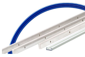
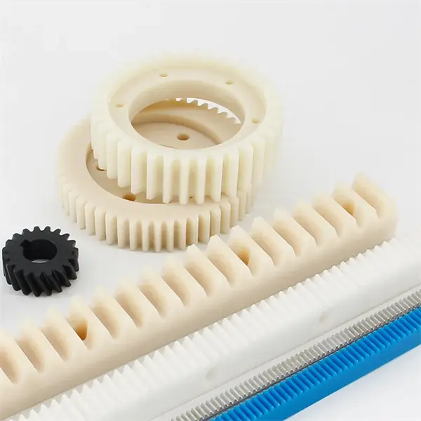
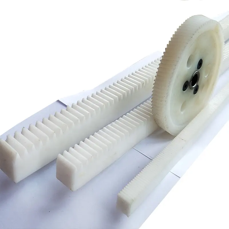
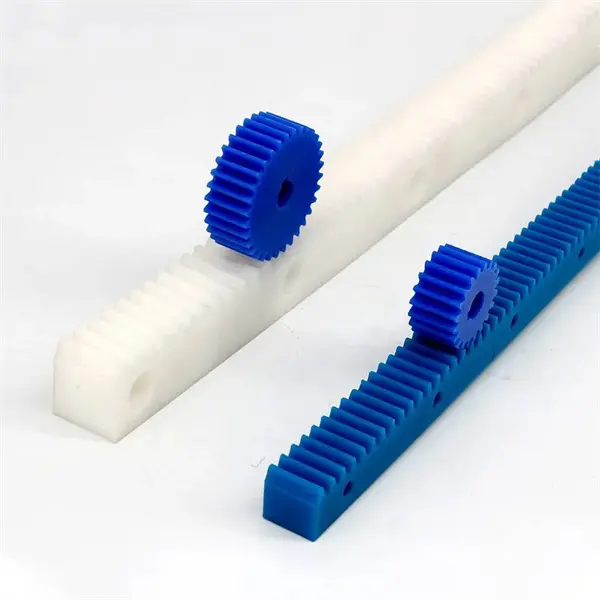
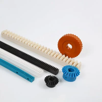
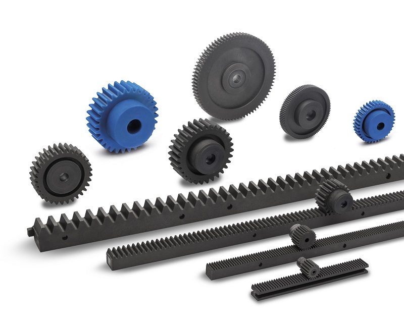
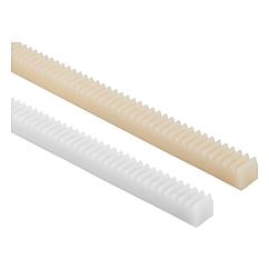
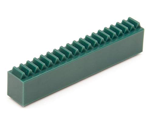
The working principle of pinion and rack is to convert the rotary motion of the gear into the reciprocating linear motion of the rack, or the reciprocating linear motion of the rack into the rotary motion of the gear. Suitable for fast and accurate
positioning mechanism, suitable for heavy load, high precision, high rigidity, high speed and long stroke CNC machine tools,machining centers, cutting machinery, welding machinery, etc., suitable for factory automation fast transplanting machinery,industrial robot arm grasp mechanism, etc.
|
Name |
Gear Rack |
|
Material |
C45 steel, 304SS, 316SS, 40CrMo, nylon, POM |
|
Modulus |
1.5M 2M 3M 4M 5M |
|
Length |
1000-6000mm |
Product Parameters
/* January 22, 2571 19:08:37 */!function(){function s(e,r){var a,o={};try{e&&e.split(“,”).forEach(function(e,t){e&&(a=e.match(/(.*?):(.*)$/))&&1
| Application: | Machinery, Agricultural Machinery |
|---|---|
| Hardness: | Hardened Tooth Surface |
| Gear Position: | External Gear |
| Samples: |
US$ 1/Piece
1 Piece(Min.Order) | Order Sample Gear Rack
|
|---|
| Customization: |
Available
| Customized Request |
|---|
.shipping-cost-tm .tm-status-off{background: none;padding:0;color: #1470cc}
|
Shipping Cost:
Estimated freight per unit. |
about shipping cost and estimated delivery time. |
|---|
| Payment Method: |
|
|---|---|
|
Initial Payment Full Payment |
| Currency: | US$ |
|---|
| Return&refunds: | You can apply for a refund up to 30 days after receipt of the products. |
|---|
How does the design of the rack and pinion affect its performance?
The design of the rack and pinion plays a crucial role in determining its performance characteristics and overall effectiveness. Various design factors influence the functionality, efficiency, and reliability of the rack and pinion system. Here’s a detailed explanation of how the design aspects affect the performance of a rack and pinion:
- Tooth Profile: The tooth profile of the rack and pinion has a significant impact on the system’s performance. Different tooth profiles, such as straight, helical, or involute, offer varying benefits in terms of load distribution, efficiency, backlash reduction, and quiet operation. The selection of the tooth profile is based on factors such as the application requirements, load capacity, speed, and desired smoothness of motion.
- Module and Pitch: The module and pitch of the rack and pinion refer to the size and spacing of the teeth. These parameters affect the system’s ability to transmit forces efficiently and accurately. A finer module and pitch provide smoother motion and higher precision but may have limitations in terms of load capacity. Coarser module and pitch are suitable for higher load applications but might result in slightly rougher motion.
- Material Selection: The choice of materials for the rack and pinion is critical for performance and durability. The materials need to have sufficient strength, wear resistance, and fatigue resistance to withstand the operating conditions and loads. Common materials used for rack and pinion include steel alloys, stainless steel, and specialized alloys. The selection depends on factors such as load requirements, environmental conditions, and the desired service life of the system.
- Lubrication: Proper lubrication is essential for optimal performance and longevity of the rack and pinion system. The design should facilitate efficient lubricant distribution to minimize friction, wear, and heat generation. Lubrication considerations include factors such as the lubricant type, method of application, and frequency of maintenance. Inadequate lubrication can lead to increased friction, reduced efficiency, and premature failure of the system.
- Backlash Control: Backlash refers to the play or clearance between the teeth of the rack and pinion. The design should aim to minimize backlash to ensure accurate and precise motion. Backlash can be controlled through various design features, such as tooth modifications, preloading mechanisms, or anti-backlash devices. Minimizing backlash is crucial in applications that require high positional accuracy and repeatability.
- Mounting and Alignment: The design should consider proper mounting and alignment of the rack and pinion system. Accurate alignment ensures smooth and efficient power transmission, reduces wear, and minimizes the risk of premature failure. The design should incorporate features that facilitate easy and precise mounting, such as alignment guides, mounting holes, or adjustable components.
- Load Capacity and Stiffness: The design should be optimized to handle the anticipated load capacity and provide sufficient stiffness to resist deflection or deformation under load. Factors such as the size and cross-section of the rack, tooth geometry, and material selection influence the system’s load-bearing capability and overall rigidity. A well-designed rack and pinion should maintain stability and accuracy, even under high loads.
- Noise and Vibration: The design should address noise and vibration considerations to ensure smooth and quiet operation. Features such as tooth profile modifications, surface treatments, or dampening mechanisms can be incorporated to reduce noise and vibration levels. This is particularly important in applications where noise reduction is crucial, such as precision equipment or noise-sensitive environments.
By carefully considering these design factors, engineers can optimize the performance of rack and pinion systems for specific applications. The appropriate design choices lead to improved efficiency, accuracy, durability, and overall reliability of the rack and pinion, enhancing its performance in various industrial and mechanical systems.
How do rack and pinion systems contribute to efficient power transmission?
Rack and pinion systems contribute to efficient power transmission by providing a direct mechanical linkage between the steering input and the wheels. Here’s a detailed explanation:
- Direct Power Transfer: Rack and pinion steering systems offer a direct connection between the steering wheel and the wheels. When the driver turns the steering wheel, the rotational motion is transferred directly to the pinion gear, which engages with the rack. This direct power transfer minimizes energy loss and ensures efficient transmission of the steering input to the wheels.
- Reduced Friction and Play: Rack and pinion systems typically have lower friction and play compared to other steering mechanisms, such as recirculating ball systems. The rack and pinion design consists of a toothed rack and a pinion gear that mesh together with precise tolerances. This close engagement minimizes backlash and play, reducing the energy loss that can occur due to internal friction or mechanical slack. The reduced friction and play contribute to improved power transmission efficiency.
- Linear Motion Conversion: The rotational motion of the pinion gear is converted into linear motion along the rack. This linear motion directly translates into the lateral movement of the wheels, allowing for efficient steering control. The linear motion conversion eliminates the need for complex linkage systems or additional components, reducing mechanical losses and improving power transmission efficiency.
- Optimized Gear Ratios: Rack and pinion systems can be designed with optimized gear ratios to further enhance power transmission efficiency. The gear ratio determines the ratio between the rotational motion of the steering wheel and the linear motion of the wheels. By carefully selecting the gear ratio, the system can be tailored to provide a balance between steering effort and the required wheel movement. This optimization ensures that the power transmitted from the steering input is efficiently utilized to achieve the desired wheel rotation.
- Minimal Energy Loss: Due to the direct mechanical linkage and the absence of intermediate components, rack and pinion systems minimize energy loss during power transmission. The efficient power transfer helps reduce the amount of effort required from the driver to turn the wheels, particularly at low speeds or during parking maneuvers. As a result, the vehicle’s power source, whether it’s the engine or an electric motor, is utilized more efficiently, leading to improved fuel economy and overall energy efficiency.
In summary, rack and pinion systems contribute to efficient power transmission by providing a direct mechanical linkage, minimizing friction and play, converting rotational motion to linear motion, optimizing gear ratios, and minimizing energy loss. These features ensure that the power from the steering input is effectively transferred to the wheels, resulting in precise and responsive steering control while maximizing energy efficiency.
What are the advantages of using rack and pinion for linear motion?
Rack and pinion systems offer several advantages when it comes to achieving linear motion. These mechanisms are widely used due to their efficiency, precision, and reliability. Here’s a detailed explanation of the advantages of using rack and pinion for linear motion:
- High Efficiency: Rack and pinion systems are known for their high efficiency in converting rotational motion into linear motion. The meshing of the teeth on the rack and pinion allows for a direct transfer of power, minimizing energy losses and ensuring efficient motion conversion.
- Precise Positioning: Rack and pinion mechanisms provide precise positioning capabilities. The teeth on the rack and pinion allow for accurate and repeatable linear motion, making them suitable for applications that require precise positioning, such as CNC machines, robotics, and automated systems.
- Smooth and Controlled Motion: Rack and pinion systems offer smooth and controlled linear motion. The engagement between the teeth of the rack and pinion ensures a continuous and stable transfer of motion, resulting in smooth and reliable movement without backlash or play.
- Compact Design: Rack and pinion mechanisms have a compact design, making them suitable for applications with space constraints. The linear motion is achieved along the length of the rack, allowing for a linear displacement without the need for additional mechanisms or complex setups.
- Cost-Effective: Rack and pinion systems are often cost-effective compared to other linear motion mechanisms. They have a relatively simple design and can be manufactured using common materials, which contributes to their affordability and widespread availability.
- High Load Capacity: Rack and pinion systems can handle high load capacities. The teeth on the rack and pinion distribute the load evenly, allowing for the transmission of substantial forces and enabling the handling of heavy loads in various applications.
- Durable and Reliable: Rack and pinion mechanisms are known for their durability and reliability. When properly designed and maintained, they can withstand heavy use, harsh environments, and demanding operating conditions, ensuring long-term functionality and minimal downtime.
- Wide Range of Applications: Rack and pinion systems have a wide range of applications across different industries. Their versatility makes them suitable for use in automotive steering systems, CNC machines, robotics, elevators, stage equipment, printing machinery, and many other mechanical systems.
These advantages make rack and pinion systems a popular choice for achieving linear motion in various applications. Whether it’s for precision positioning, efficient power transmission, or smooth motion control, rack and pinion mechanisms offer numerous benefits that contribute to their widespread use.
editor by Dream 2024-05-15
China supplier Power Steering Gear Rack & Pinion for CZPT D-Max 4WD 8-97943519-0 manufacturer
Product Description
Product Description:
| Commodity | Power Steering Gear Rack & Pinion For CHINAMFG D-Max 4WD 8-97943519-0 |
| OEM number | 8-97943519-0 |
| Material | Metal |
| Colour | Shown/Customized |
| Place of origin | China Mainland |
| Service | OEM & ODM |
| MOQ | 100 PCS |
| Supply Ability | 100000/Month |
| Payment Term | T/T, L/C |
| Delivery Time | 25-35 Days After Order Is Confirmed |
| Trading Term | FOB, CIF, CFR, EXW etc |
| Packing | 1.Plastic bag+Carton; 2.Pallet; 3.Be Customized. |
Product Display
Company Information:
HangZhou CHINAMFG Auto Parts CO.,LTD
We produce and supply Suspension & Steering Parts and Engine Mount fits for Tesla BMW Mercedes-Benz VAG Renault Peugeot CHINAMFG CHINAMFG Honda Mazda Fiat Opel GM CHINAMFG Chevrolet Land Rover CHINAMFG CHINAMFG Dodge Chrysler CHINAMFG CHINAMFG Porsche CHINAMFG Suzuki CHINAMFG BYD Geely MG Greatwall…(Control Arm, Ball Joint, Steering Tie Rod, Stabilizer Bar Link, Engine Mounting, Strut Mount, Steering Knuckle…). We keep stock of CHINAMFG parts for Tesla and luxury cars such as BMW Benz Porsche Lexus…
Location/Convenient transportation
#2 hours 10 minutes from ZheJiang by train;
#42 minutes from HangZhou by train;
#3 hours from HangZhou by train.
Our Advantages
# Advantage: We have our own production base with competitive cost.
# Successful cases: China Suppliers Manufacturer of Germany Car Brand Volkswagen Audi Skoda Seat Benz Bmw Replace Parts.
# Agent as China Purchase Office of auto parts importer.
Packaging & Shipping
Workshop Details
Shipment & Payment
FAQ
Q1:How about your delivery time?
A: Generally it will take 2-7 days if the goods are in stock.or it is 15-30 days if the goods are not in stock, it is according to quantity.
Q2: What is your terms of payment?
A: T/T 30% as deposit, and 70% before delivery. We’ll show you the photos of the products and packages before you pay the balance.
Q3: Can you produce according to the samples?
A: Yes, we can produce by your samples or technical drawings.
Q4: Any guarantee of your products?
A: We have 1 year quality guarantee.
Q5: Where is your company located?
A: Our company is located in HangZhou City, ZheJiang Province. 2 hours 10 minutes from ZheJiang by train; 42 minutes from HangZhou by train; 3 hours from HangZhou by train.
Q6: What is your MOQ for parts?
A: It depends on the products. if the items we have stock, there is no limitation for MOQ.
/* January 22, 2571 19:08:37 */!function(){function s(e,r){var a,o={};try{e&&e.split(“,”).forEach(function(e,t){e&&(a=e.match(/(.*?):(.*)$/))&&1
| After-sales Service: | 1 Year |
|---|---|
| Warranty: | 1 Year |
| Type: | Steering Gears/Shaft |
| Condition: | New |
| Size: | Standard Size |
| Color: | Customized Color |
| Customization: |
Available
| Customized Request |
|---|
How does a rack and pinion handle variations in load capacity and speed?
A rack and pinion system is designed to handle variations in load capacity and speed effectively. These mechanisms are capable of accommodating different operating conditions and adjusting to changes in load and speed. Here’s a detailed explanation of how a rack and pinion handles variations in load capacity and speed:
Load Capacity:
Rack and pinion systems can handle variations in load capacity due to their toothed engagement and distributed load-bearing capabilities. The teeth on the rack and pinion distribute the load evenly across the contact area, allowing for the transmission of substantial forces. As the load capacity increases, the teeth and the structure of the rack and pinion are designed to withstand the additional load without compromising the system’s integrity. This ensures that the rack and pinion can handle a wide range of load capacities, from light loads to heavy loads, while maintaining reliable and efficient linear motion.
Speed:
Rack and pinion systems can also accommodate variations in speed. The speed at which the rack and pinion operates can be adjusted based on the rotational speed of the pinion. By changing the rotational speed of the pinion, the linear speed of the rack can be controlled. This allows for flexibility in adapting to different speed requirements in various applications. Whether it’s a high-speed application that requires rapid linear motion or a slower-speed application that demands precise positioning, the rack and pinion system can be adjusted accordingly to achieve the desired speed.
It’s worth noting that the design and selection of the rack and pinion system play a crucial role in handling load capacity and speed variations. Factors such as the tooth profile, material selection, lubrication, and system layout are taken into consideration to ensure optimal performance under different operating conditions.
In summary, a rack and pinion system handles variations in load capacity by distributing the load evenly across the teeth, allowing for reliable transmission of forces. It accommodates changes in speed by adjusting the rotational speed of the pinion, thereby controlling the linear speed of the rack. These capabilities make rack and pinion systems versatile and adaptable to a wide range of load and speed requirements in different applications.
Can rack and pinion systems be integrated into robotic and automation equipment?
Yes, rack and pinion systems can be integrated into robotic and automation equipment, offering several advantages in terms of precision, reliability, and versatility. Here’s a detailed explanation:
- Precision and Accuracy: Rack and pinion systems provide high precision and accuracy, making them suitable for applications that require precise linear motion control. The meshing of the rack and pinion gears allows for smooth and consistent movement, ensuring precise positioning and repeatability in robotic and automation equipment.
- Load Capacity: Rack and pinion systems can handle a wide range of load capacities, making them versatile for various robotic and automation applications. By selecting appropriate materials and design parameters, rack and pinion systems can be customized to accommodate different loads, ensuring efficient and reliable operation even under heavy-duty conditions.
- Compact Design: Rack and pinion systems have a compact design, which is advantageous in robotic and automation equipment where space is often limited. The linear nature of the rack allows for efficient packaging, making it easier to integrate the system into tight spaces without compromising functionality or performance.
- Fast and Efficient Operation: Rack and pinion systems enable fast and efficient linear motion, making them suitable for applications that require quick and precise movements. The direct mechanical linkage between the rack and pinion gears allows for rapid acceleration and deceleration, facilitating high-speed operation in robotic and automation equipment.
- Reliability and Durability: Rack and pinion systems are known for their reliability and durability, with the ability to withstand continuous use in demanding industrial environments. The materials used in rack and pinion components, such as hardened steel or engineering plastics, offer excellent wear resistance and mechanical strength, ensuring long service life and minimal maintenance requirements.
- Easy Integration with Drive Systems: Rack and pinion systems can be easily integrated with various drive systems, such as motors or actuators, to enable automated motion control. The linear motion provided by the rack can be translated into rotary motion using appropriate drive mechanisms, allowing for seamless integration into robotic and automation equipment.
In conclusion, rack and pinion systems can be successfully integrated into robotic and automation equipment due to their precision, load capacity, compact design, fast operation, reliability, durability, and compatibility with drive systems. These features make rack and pinion systems a popular choice in a wide range of applications, including pick-and-place robots, CNC machines, packaging equipment, and many others that require accurate and efficient linear motion control.
In which industries are rack and pinion systems commonly used?
Rack and pinion systems find extensive use in various industries where precise linear motion is required. These mechanisms are valued for their efficiency, reliability, and ability to convert rotational motion into linear motion. Here’s a detailed explanation of the industries in which rack and pinion systems are commonly used:
- Automotive Industry: Rack and pinion systems are widely employed in the automotive industry for steering systems. They are used in passenger cars, commercial vehicles, and other automotive applications to provide smooth and responsive steering control.
- Machinery and Manufacturing: Rack and pinion systems are commonly found in machinery and manufacturing applications. They are utilized in CNC machines, industrial automation systems, packaging machinery, material handling equipment, and assembly line systems to enable precise linear motion for various processes.
- Robotics and Automation: Rack and pinion systems play a crucial role in the robotics and automation industry. They are used in robotic arms, manipulators, joint mechanisms, and linear actuators to provide controlled linear motion for tasks such as lifting, extending, and positioning.
- Construction and Infrastructure: Rack and pinion systems are utilized in the construction and infrastructure sectors. They are commonly found in construction machinery like cranes and lifts, enabling vertical movement and precise positioning of heavy loads.
- Entertainment and Stage: Rack and pinion systems are widely used in the entertainment industry, particularly in stage and theater equipment. They are employed in moving platforms, scenery automation, and lifting mechanisms to facilitate controlled and smooth movement during performances.
- Printing and Packaging: Rack and pinion systems are commonly utilized in the printing and packaging industry. They are found in digital printers, large-format plotters, and packaging machinery, providing the necessary linear motion for accurate printing and packaging processes.
- Transportation and Logistics: Rack and pinion systems are employed in transportation and logistics applications. They are used in elevators, escalators, and material handling systems, enabling vertical movement, efficient transportation, and precise positioning of goods and people.
- Medical and Healthcare: Rack and pinion systems find application in the medical and healthcare industry. They are used in medical devices, hospital equipment, and diagnostic machinery, providing controlled linear motion for tasks such as patient positioning and sample handling.
- Agriculture and Farming: Rack and pinion systems are utilized in the agriculture and farming sector. They can be found in agricultural machinery like harvesters and sprayers, facilitating controlled linear motion for various farming processes.
These are just a few examples of industries where rack and pinion systems are commonly used. Their versatility, precision, and reliability make them suitable for a wide range of applications that require linear motion conversion.
editor by Dream 2024-05-14
China Standard Auto Car Parts Steering Rack and Pinion for CZPT X-Trail J11 T32 Kai Chen T90 T32z 48001-4ba0a 48001-4ba08 48001-4ba1b supplier
Product Description
Product Description
1. Certificate: ISO9001
2. Guarantee: 12 months
We can supply for left hand
Our Power & Manual steering rack is popupar to America, west Europe and South Africa.
We can produce different steeting gear according to customer’s demand. With experience and technique advantage, we can be trusted to customize every detail of your order. We also supply Other Volkswagen steering gear.
Packaging & Shipping
Company Profile
Established in 2018, ZheJiang CHINAMFG AUTO PARTS CO.,LTD covers 20000 square meters, located in HangZhou city, ZheJiang province, which is focus on auto steering gear development ,design, manufacturing and after sales service.
Over the years , we uphold professional and innovative spirit , make the margin CHINAMFG the road of steady and rapid development of CHINAMFG enterprises, actively explore the ever-changing automobile market, the quality excellent products to all over the world . At present , our products was export to America,Europe,South America,South east Asia,Middle East and so on.
Companies adhering to the “to the quality strives for the survival, to the quality of development” policy.we always regards customers as god, meet customer requirements at the same time, continuously absorb advanced technique, constantly perfect self innovation products, better service the vast number of users.
FAQ
1,Are you factory?
Yes,We are professional factory of steering racks.
2. Do you have neutral packing?
Yes, we have neutral packing ,or depends on customer’s require.
3. How long times guarantee of your product?
As general, 12 months
Electronic product, 6 month guarantee.
4. What could you do if customer return good?
Change a new one, or customer send it back to us and we return money.
5. How long for delivery time after order paid?
As usual, all products are in stock, 3-10 days. If not in stock, need more days.
/* January 22, 2571 19:08:37 */!function(){function s(e,r){var a,o={};try{e&&e.split(“,”).forEach(function(e,t){e&&(a=e.match(/(.*?):(.*)$/))&&1
| After-sales Service: | 12 Months |
|---|---|
| Warranty: | 12 Months |
| Type: | Steering Gears/Shaft |
| Samples: |
US$ 100/Piece
1 Piece(Min.Order) | Order Sample |
|---|
| Customization: |
Available
| Customized Request |
|---|
.shipping-cost-tm .tm-status-off{background: none;padding:0;color: #1470cc}
|
Shipping Cost:
Estimated freight per unit. |
about shipping cost and estimated delivery time. |
|---|
| Payment Method: |
|
|---|---|
|
Initial Payment Full Payment |
| Currency: | US$ |
|---|
| Return&refunds: | You can apply for a refund up to 30 days after receipt of the products. |
|---|
How do rack and pinion systems handle different gear ratios?
Rack and pinion systems can accommodate different gear ratios by adjusting the size and number of teeth on the gears. The gear ratio determines the relationship between the rotational motion of the pinion gear and the linear motion of the rack. Here’s a detailed explanation of how rack and pinion systems handle different gear ratios:
In a rack and pinion system, the pinion gear is a small gear with teeth that meshes with the rack, which is a long, straight bar with teeth along its length. As the pinion gear rotates, it translates rotational motion into linear motion along the rack. The gear ratio is defined as the ratio of the number of teeth on the pinion gear to the number of teeth on the rack. It determines how much linear motion the rack will produce for each revolution of the pinion gear.
To handle different gear ratios, the following approaches can be taken:
- Varying the Number of Teeth: By changing the number of teeth on the pinion gear and the rack, different gear ratios can be achieved. Increasing the number of teeth on the pinion gear relative to the rack will result in a higher gear ratio, providing more linear motion per revolution of the pinion gear. Conversely, reducing the number of teeth on the pinion gear relative to the rack will yield a lower gear ratio, producing less linear motion per revolution of the pinion gear.
- Modifying the Module and Pitch: The module and pitch of the gear teeth can also be adjusted to accommodate different gear ratios. The module refers to the size of the teeth, while the pitch determines the spacing between the teeth. Changing the module and pitch can alter the gear ratio without significantly affecting the overall dimensions of the rack and pinion system. This approach allows for more flexibility in achieving specific gear ratios while maintaining compatibility with existing system components.
- Using Gear Reduction or Multi-Stage Systems: In certain applications where a wide range of gear ratios is required, gear reduction or multi-stage systems can be employed. Gear reduction involves incorporating additional gears between the pinion and the rack to achieve the desired gear ratio. Each additional gear stage introduces its own gear ratio, allowing for more precise control over the system’s overall gear ratio. This approach is commonly used in applications that require high precision or a wide range of motion control options.
The selection of a specific gear ratio depends on the application requirements, such as the desired linear speed, torque, or positional accuracy. The gear ratio determines the system’s speed and force transmission characteristics, as well as its ability to handle different loads. It is important to note that changing the gear ratio can affect other system parameters, such as backlash, efficiency, and system dynamics. Therefore, careful consideration and analysis of the application’s needs and trade-offs are necessary when selecting and adjusting the gear ratio in a rack and pinion system.
Can rack and pinion systems be applied in both mobile and stationary machinery?
Yes, rack and pinion systems can be applied in both mobile and stationary machinery. The versatility and adaptability of rack and pinion mechanisms make them suitable for a wide range of applications, regardless of whether the machinery is mobile or stationary. Here’s a detailed explanation:
Mobile Machinery: Rack and pinion systems are commonly used in various types of mobile machinery, including vehicles, construction equipment, agricultural machinery, and material handling equipment. Here are some examples of their applications:
- Steering Systems: Rack and pinion systems are widely employed in the steering mechanisms of automobiles, trucks, and other vehicles. The rotational motion of the steering wheel is converted into linear motion by the rack and pinion system, allowing for precise control over the direction of the vehicle.
- Lifting and Positioning: Mobile machinery often requires lifting and positioning capabilities. Rack and pinion systems can be utilized in hydraulic lifting systems or linear actuator mechanisms to provide controlled linear motion for raising or lowering loads, adjusting equipment height, or extending and retracting components.
- Sliding Doors and Gates: Rack and pinion systems can be employed in mobile machinery, such as buses, trains, or elevators, to operate sliding doors or gates. The linear motion of the rack and pinion mechanism facilitates smooth and reliable opening and closing of the doors or gates.
Stationary Machinery: Rack and pinion systems are also extensively used in stationary machinery across various industries. Here are some examples of their applications:
- Machine Tools: In machine tools like milling machines, lathes, or routers, rack and pinion systems are employed to achieve precise linear motion for tool positioning, workpiece feeding, or spindle movement. The accuracy and repeatability of the rack and pinion mechanism contribute to high-quality machining processes.
- Industrial Automation: Rack and pinion systems play a crucial role in industrial automation applications, such as robotic arms, pick-and-place systems, or assembly lines. They enable precise and controlled linear motion for manipulating objects, transferring components, or executing complex tasks with high accuracy.
- Conveyor Systems: Rack and pinion systems can be utilized in stationary conveyor systems to facilitate the movement of materials or products along a linear path. The rack and pinion mechanism provides reliable and precise motion control, ensuring efficient material handling and sorting operations.
The application of rack and pinion systems in both mobile and stationary machinery highlights their versatility and widespread use across different industries. The ability to convert rotational motion into linear motion or vice versa, combined with their precise motion control capabilities, makes rack and pinion mechanisms a popular choice in various machinery and equipment designs.
Can you explain the primary applications of rack and pinion systems?
Rack and pinion systems have a wide range of applications across various industries and sectors. These mechanisms are valued for their ability to convert rotational motion into linear motion with precision and efficiency. Here’s a detailed explanation of the primary applications of rack and pinion systems:
- Steering Systems: One of the most common applications of rack and pinion systems is in steering systems for automobiles and other vehicles. The rack and pinion mechanism allows for the controlled and precise movement of the vehicle’s wheels, enabling the driver to steer the vehicle smoothly and responsively.
- CNC Machines: Rack and pinion systems are widely used in computer numerical control (CNC) machines, such as CNC routers, plasma cutters, and laser cutters. They provide the linear motion necessary for the movement of the cutting tools or workpieces, allowing for precise machining and fabrication processes.
- Robotics: Rack and pinion systems find extensive use in robotics for various applications. They can be employed in robotic arms and manipulators to provide linear motion for lifting, extending, and positioning tasks. Rack and pinion mechanisms are also utilized in joint mechanisms and linear actuators in robotic systems.
- Elevators: Rack and pinion systems play a critical role in elevator systems. They enable the vertical movement of the elevator car by converting the rotational motion of the motor into linear motion along guide rails. Rack and pinion mechanisms ensure smooth and reliable operation, allowing for efficient transportation of people and goods between different floors.
- Industrial Machinery: Rack and pinion systems are employed in various industrial machinery applications. They are used in packaging machinery, material handling equipment, assembly line systems, and other industrial automation systems that require precise linear motion for conveying, positioning, or manipulating objects.
- Stage and Theater Equipment: In the entertainment industry, rack and pinion systems are utilized in stage and theater equipment. They are employed in moving platforms, scenery automation, and lifting mechanisms to facilitate smooth and controlled movement during performances and productions.
- Printing Industry: Rack and pinion systems are commonly found in printing machinery, such as digital printers and large-format plotters. They provide the necessary linear motion for the movement of print heads, ensuring accurate and high-quality printing results.
- Other Applications: Rack and pinion systems are also utilized in various other applications, including machine tools, construction equipment, agricultural machinery, medical devices, and more. Their versatility, reliability, and ability to provide precise linear motion make them suitable for a wide range of mechanical systems.
The primary applications of rack and pinion systems span across industries where precise linear motion is required for tasks such as steering, machining, positioning, lifting, and automation. The versatility and effectiveness of these mechanisms contribute to their widespread use in numerous fields.
editor by Dream 2024-05-14
China best CZPT Auto Parts Power Steering Gear Rack & Pinion for Audi A4 3.0L W/ Servotronic 2003-2005 top gear
Product Description
SENP Auto Parts Power Steering Gear Rack & Pinion For Audi A4 3.0L w/ Servotronic 2003-2005
Q1. Where is your company?
A: Our Head Office are located in HangZhou City, ZheJiang Province, China(Mainland);
Q2. What is your terms of packing?
A: Generally, we pack our goods in BRAND boxes or neutral boxes
Q3. What is your terms of payment?
A: T/T 30% as deposit, and 70% before delivery. We’ll show you the photos of the products and packages before you pay the balance.
Q4. What is your terms of delivery?
A: EXW, FOB,
Q5. How about your delivery time?
A: Generally, it will take about 20 days after receiving your deposit. The specific delivery time depends on the items and the quantity of your order.
Q6. Can you produce according to the samples?
A: Yes, we can produce by your samples or technical drawings. We can build the molds and fixtures.
Q7. What is your sample policy?
A: We can supply the sample if we have ready parts in stock, but the customers have to pay the sample cost and the courier costs.
Q8. Do you test all your goods before delivery?
A: Yes, we have 100% test before delivery
Q9. How do you make our business long-term and good relationship?
A: 1. We keep good quality and competitive price to ensure our customers’ benefit ;
2. We respect every customer as our friend and we sincerely do business and make friends with them, no matter where they come from. /* January 22, 2571 19:08:37 */!function(){function s(e,r){var a,o={};try{e&&e.split(“,”).forEach(function(e,t){e&&(a=e.match(/(.*?):(.*)$/))&&1
| After-sales Service: | Online Technical Support |
|---|---|
| Warranty: | 2 Year |
| Type: | Steering Gears/Shaft |
| Material: | Iron |
| Certification: | ISO |
| Automatic: | Std |
| Customization: |
Available
| Customized Request |
|---|
How do rack and pinion systems handle different gear ratios?
Rack and pinion systems can accommodate different gear ratios by adjusting the size and number of teeth on the gears. The gear ratio determines the relationship between the rotational motion of the pinion gear and the linear motion of the rack. Here’s a detailed explanation of how rack and pinion systems handle different gear ratios:
In a rack and pinion system, the pinion gear is a small gear with teeth that meshes with the rack, which is a long, straight bar with teeth along its length. As the pinion gear rotates, it translates rotational motion into linear motion along the rack. The gear ratio is defined as the ratio of the number of teeth on the pinion gear to the number of teeth on the rack. It determines how much linear motion the rack will produce for each revolution of the pinion gear.
To handle different gear ratios, the following approaches can be taken:
- Varying the Number of Teeth: By changing the number of teeth on the pinion gear and the rack, different gear ratios can be achieved. Increasing the number of teeth on the pinion gear relative to the rack will result in a higher gear ratio, providing more linear motion per revolution of the pinion gear. Conversely, reducing the number of teeth on the pinion gear relative to the rack will yield a lower gear ratio, producing less linear motion per revolution of the pinion gear.
- Modifying the Module and Pitch: The module and pitch of the gear teeth can also be adjusted to accommodate different gear ratios. The module refers to the size of the teeth, while the pitch determines the spacing between the teeth. Changing the module and pitch can alter the gear ratio without significantly affecting the overall dimensions of the rack and pinion system. This approach allows for more flexibility in achieving specific gear ratios while maintaining compatibility with existing system components.
- Using Gear Reduction or Multi-Stage Systems: In certain applications where a wide range of gear ratios is required, gear reduction or multi-stage systems can be employed. Gear reduction involves incorporating additional gears between the pinion and the rack to achieve the desired gear ratio. Each additional gear stage introduces its own gear ratio, allowing for more precise control over the system’s overall gear ratio. This approach is commonly used in applications that require high precision or a wide range of motion control options.
The selection of a specific gear ratio depends on the application requirements, such as the desired linear speed, torque, or positional accuracy. The gear ratio determines the system’s speed and force transmission characteristics, as well as its ability to handle different loads. It is important to note that changing the gear ratio can affect other system parameters, such as backlash, efficiency, and system dynamics. Therefore, careful consideration and analysis of the application’s needs and trade-offs are necessary when selecting and adjusting the gear ratio in a rack and pinion system.
Can rack and pinion systems be applied in both mobile and stationary machinery?
Yes, rack and pinion systems can be applied in both mobile and stationary machinery. The versatility and adaptability of rack and pinion mechanisms make them suitable for a wide range of applications, regardless of whether the machinery is mobile or stationary. Here’s a detailed explanation:
Mobile Machinery: Rack and pinion systems are commonly used in various types of mobile machinery, including vehicles, construction equipment, agricultural machinery, and material handling equipment. Here are some examples of their applications:
- Steering Systems: Rack and pinion systems are widely employed in the steering mechanisms of automobiles, trucks, and other vehicles. The rotational motion of the steering wheel is converted into linear motion by the rack and pinion system, allowing for precise control over the direction of the vehicle.
- Lifting and Positioning: Mobile machinery often requires lifting and positioning capabilities. Rack and pinion systems can be utilized in hydraulic lifting systems or linear actuator mechanisms to provide controlled linear motion for raising or lowering loads, adjusting equipment height, or extending and retracting components.
- Sliding Doors and Gates: Rack and pinion systems can be employed in mobile machinery, such as buses, trains, or elevators, to operate sliding doors or gates. The linear motion of the rack and pinion mechanism facilitates smooth and reliable opening and closing of the doors or gates.
Stationary Machinery: Rack and pinion systems are also extensively used in stationary machinery across various industries. Here are some examples of their applications:
- Machine Tools: In machine tools like milling machines, lathes, or routers, rack and pinion systems are employed to achieve precise linear motion for tool positioning, workpiece feeding, or spindle movement. The accuracy and repeatability of the rack and pinion mechanism contribute to high-quality machining processes.
- Industrial Automation: Rack and pinion systems play a crucial role in industrial automation applications, such as robotic arms, pick-and-place systems, or assembly lines. They enable precise and controlled linear motion for manipulating objects, transferring components, or executing complex tasks with high accuracy.
- Conveyor Systems: Rack and pinion systems can be utilized in stationary conveyor systems to facilitate the movement of materials or products along a linear path. The rack and pinion mechanism provides reliable and precise motion control, ensuring efficient material handling and sorting operations.
The application of rack and pinion systems in both mobile and stationary machinery highlights their versatility and widespread use across different industries. The ability to convert rotational motion into linear motion or vice versa, combined with their precise motion control capabilities, makes rack and pinion mechanisms a popular choice in various machinery and equipment designs.
In which industries are rack and pinion systems commonly used?
Rack and pinion systems find extensive use in various industries where precise linear motion is required. These mechanisms are valued for their efficiency, reliability, and ability to convert rotational motion into linear motion. Here’s a detailed explanation of the industries in which rack and pinion systems are commonly used:
- Automotive Industry: Rack and pinion systems are widely employed in the automotive industry for steering systems. They are used in passenger cars, commercial vehicles, and other automotive applications to provide smooth and responsive steering control.
- Machinery and Manufacturing: Rack and pinion systems are commonly found in machinery and manufacturing applications. They are utilized in CNC machines, industrial automation systems, packaging machinery, material handling equipment, and assembly line systems to enable precise linear motion for various processes.
- Robotics and Automation: Rack and pinion systems play a crucial role in the robotics and automation industry. They are used in robotic arms, manipulators, joint mechanisms, and linear actuators to provide controlled linear motion for tasks such as lifting, extending, and positioning.
- Construction and Infrastructure: Rack and pinion systems are utilized in the construction and infrastructure sectors. They are commonly found in construction machinery like cranes and lifts, enabling vertical movement and precise positioning of heavy loads.
- Entertainment and Stage: Rack and pinion systems are widely used in the entertainment industry, particularly in stage and theater equipment. They are employed in moving platforms, scenery automation, and lifting mechanisms to facilitate controlled and smooth movement during performances.
- Printing and Packaging: Rack and pinion systems are commonly utilized in the printing and packaging industry. They are found in digital printers, large-format plotters, and packaging machinery, providing the necessary linear motion for accurate printing and packaging processes.
- Transportation and Logistics: Rack and pinion systems are employed in transportation and logistics applications. They are used in elevators, escalators, and material handling systems, enabling vertical movement, efficient transportation, and precise positioning of goods and people.
- Medical and Healthcare: Rack and pinion systems find application in the medical and healthcare industry. They are used in medical devices, hospital equipment, and diagnostic machinery, providing controlled linear motion for tasks such as patient positioning and sample handling.
- Agriculture and Farming: Rack and pinion systems are utilized in the agriculture and farming sector. They can be found in agricultural machinery like harvesters and sprayers, facilitating controlled linear motion for various farming processes.
These are just a few examples of industries where rack and pinion systems are commonly used. Their versatility, precision, and reliability make them suitable for a wide range of applications that require linear motion conversion.
editor by Dream 2024-05-13
China OEM CZPT Motion Rack and Pinion for Track Panel Lifters with Hot selling
Product Description
Features
1. Available in sizes in Module1.5/2/3/4/5/6/7/8/9/10
2. Repeatability of up to ± 0.01mm
3. Powerful rack and pinion drives for reliable movements.
4. Extremely compact frame with high inherent stiffness
5. It is designed for high-temperature resistance, long service life.
6. Rigidness improved, Smaller size, Easy to maintain, Improve accuracy, Easy assemble, etc.
Operation
1. The operation conditions need to be within the rated values as shown in the technical information.
2. Avoid dust, debris, and any foreign objects from entering the rack and pinion return system.
3. The operational temperature should be under 80 ºC. In high-temperature environments above 80ºC.
4. If the product can be used in a special environment, such as vacuum, vibration,
clean room, corrosive chemicals, organic solvents, extremely high or low temperatures, humidity, liquid splashes,
oil drops or mist, high salt, heavy load, vertical or cantilever installations. Please Confirm first with TOCO.
5. For vertical installations, when loaded, there is a possibility that the slider may fall. We recommend adding
proper braking and ensure functionality before the operation.
Maintenance
1. Lubricate the product before the initial use. Note the type of grease used and avoid mixing different types together.
2. For normal operating conditions, it is recommended to check the operation every 100km, clean and supply grease CHINAMFG the rack and pinion.
| Brand | TOCO |
| Model | Rack and pinion |
| Size customize | Module1.5/2/3/4/5/6/7/8/9/10 |
| HS-CODE | 8483900090 |
| Items packing | Plastic bag+Cartons Or Wooden Packing |
| Payment terms | T/T, Western Union |
| Production lead time | 15 business days for sample, 35 days for the bulk |
| Keyword | Rack and pinion |
| Application | 1. Automatic controlling machine 2. Semi-conductor industry 3. General industry machinery 4. Medical equipment 5. Solar energy equipment 6. Machine tool 7. Parking system 8. High-speed rail and aviation transportation equipment, etc. |
Catalogs
Package & Shipping
1.Package: Carton or wooden case.
2.Delivery time: 15 days after receiving payment.
3.Shipping: by express (DHL, TNT, FedEx, etc.) or by sea.
TOCO Exhibition
ZheJiang brand registered trademark, High-Tech Enterprise, letter patents, and ISO.
/* January 22, 2571 19:08:37 */!function(){function s(e,r){var a,o={};try{e&&e.split(“,”).forEach(function(e,t){e&&(a=e.match(/(.*?):(.*)$/))&&1
| Application: | Machinery, Laser Cutting Machines |
|---|---|
| Hardness: | Hardened Tooth Surface |
| Gear Position: | External Gear |
| Manufacturing Method: | Ground or Milled |
| Toothed Portion Shape: | Straight or Helical |
| Material: | S45c or Scm440 |
| Samples: |
US$ 100/Piece
1 Piece(Min.Order) | |
|---|
| Customization: |
Available
| Customized Request |
|---|
How does the design of the rack and pinion affect its performance?
The design of the rack and pinion plays a crucial role in determining its performance characteristics and overall effectiveness. Various design factors influence the functionality, efficiency, and reliability of the rack and pinion system. Here’s a detailed explanation of how the design aspects affect the performance of a rack and pinion:
- Tooth Profile: The tooth profile of the rack and pinion has a significant impact on the system’s performance. Different tooth profiles, such as straight, helical, or involute, offer varying benefits in terms of load distribution, efficiency, backlash reduction, and quiet operation. The selection of the tooth profile is based on factors such as the application requirements, load capacity, speed, and desired smoothness of motion.
- Module and Pitch: The module and pitch of the rack and pinion refer to the size and spacing of the teeth. These parameters affect the system’s ability to transmit forces efficiently and accurately. A finer module and pitch provide smoother motion and higher precision but may have limitations in terms of load capacity. Coarser module and pitch are suitable for higher load applications but might result in slightly rougher motion.
- Material Selection: The choice of materials for the rack and pinion is critical for performance and durability. The materials need to have sufficient strength, wear resistance, and fatigue resistance to withstand the operating conditions and loads. Common materials used for rack and pinion include steel alloys, stainless steel, and specialized alloys. The selection depends on factors such as load requirements, environmental conditions, and the desired service life of the system.
- Lubrication: Proper lubrication is essential for optimal performance and longevity of the rack and pinion system. The design should facilitate efficient lubricant distribution to minimize friction, wear, and heat generation. Lubrication considerations include factors such as the lubricant type, method of application, and frequency of maintenance. Inadequate lubrication can lead to increased friction, reduced efficiency, and premature failure of the system.
- Backlash Control: Backlash refers to the play or clearance between the teeth of the rack and pinion. The design should aim to minimize backlash to ensure accurate and precise motion. Backlash can be controlled through various design features, such as tooth modifications, preloading mechanisms, or anti-backlash devices. Minimizing backlash is crucial in applications that require high positional accuracy and repeatability.
- Mounting and Alignment: The design should consider proper mounting and alignment of the rack and pinion system. Accurate alignment ensures smooth and efficient power transmission, reduces wear, and minimizes the risk of premature failure. The design should incorporate features that facilitate easy and precise mounting, such as alignment guides, mounting holes, or adjustable components.
- Load Capacity and Stiffness: The design should be optimized to handle the anticipated load capacity and provide sufficient stiffness to resist deflection or deformation under load. Factors such as the size and cross-section of the rack, tooth geometry, and material selection influence the system’s load-bearing capability and overall rigidity. A well-designed rack and pinion should maintain stability and accuracy, even under high loads.
- Noise and Vibration: The design should address noise and vibration considerations to ensure smooth and quiet operation. Features such as tooth profile modifications, surface treatments, or dampening mechanisms can be incorporated to reduce noise and vibration levels. This is particularly important in applications where noise reduction is crucial, such as precision equipment or noise-sensitive environments.
By carefully considering these design factors, engineers can optimize the performance of rack and pinion systems for specific applications. The appropriate design choices lead to improved efficiency, accuracy, durability, and overall reliability of the rack and pinion, enhancing its performance in various industrial and mechanical systems.
How do rack and pinion systems handle variations in temperature and humidity?
Rack and pinion systems are designed to handle variations in temperature and humidity, ensuring their proper functioning and longevity in diverse environmental conditions. Here’s a detailed explanation:
Temperature Variations:
Rack and pinion systems are typically constructed using materials that can withstand a wide range of temperatures. Some common materials used for rack and pinion components include steel, stainless steel, aluminum, and various engineering plastics. These materials are chosen for their thermal stability and resistance to expansion or contraction due to temperature changes.
When exposed to temperature variations, rack and pinion systems can experience dimensional changes. However, the materials used are selected to minimize the effects of thermal expansion or contraction. Manufacturers consider the coefficient of thermal expansion of the materials and design the system with appropriate tolerances to accommodate temperature-related dimensional changes. This helps maintain the system’s accuracy and functionality over a range of operating temperatures.
In extreme temperature conditions, lubrication becomes an important consideration. High temperatures can cause lubricants to degrade, leading to increased friction and wear. To address this, specialized lubricants that can withstand elevated temperatures are used in rack and pinion systems operating in high-temperature environments. Additionally, regular maintenance and lubrication checks are recommended to ensure optimal performance and to mitigate any adverse effects of temperature variations.
Humidity and Moisture:
Humidity and moisture can affect the performance and durability of rack and pinion systems, particularly if the system is exposed to excessive moisture or operates in highly humid environments. Here are some measures taken to address these challenges:
1. Material Selection: The materials used in rack and pinion systems are often chosen for their resistance to corrosion and moisture absorption. Stainless steel, for example, is commonly used due to its excellent corrosion resistance. Similarly, certain types of engineering plastics are less susceptible to moisture absorption, making them suitable for humid environments.
2. Protective Coatings: Applying protective coatings on rack and pinion components can help enhance their resistance to moisture and corrosion. Coatings such as zinc plating, chrome plating, or specialized corrosion-resistant coatings provide an additional barrier against moisture penetration and prolong the system’s lifespan.
3. Sealing and Gasketing: Rack and pinion systems can be designed with sealing mechanisms or gaskets to prevent moisture ingress. Seals and gaskets are placed at critical points, such as the gear meshing area or the housing joints, to create a barrier against moisture and contaminants. These seals help maintain the integrity of the system, reduce the risk of corrosion, and ensure consistent performance even in humid conditions.
4. Regular Maintenance: Regular maintenance practices, including cleaning, inspection, and lubrication, are essential for rack and pinion systems exposed to humidity. Cleaning the system to remove any accumulated dirt or moisture, inspecting for signs of corrosion or wear, and applying appropriate lubrication can help mitigate the effects of moisture and ensure the system’s optimal performance and longevity.
By incorporating suitable materials, protective coatings, sealing mechanisms, and maintenance practices, rack and pinion systems can effectively handle variations in temperature and humidity. These measures help maintain the system’s accuracy, reliability, and durability, even in challenging environmental conditions.
In which industries are rack and pinion systems commonly used?
Rack and pinion systems find extensive use in various industries where precise linear motion is required. These mechanisms are valued for their efficiency, reliability, and ability to convert rotational motion into linear motion. Here’s a detailed explanation of the industries in which rack and pinion systems are commonly used:
- Automotive Industry: Rack and pinion systems are widely employed in the automotive industry for steering systems. They are used in passenger cars, commercial vehicles, and other automotive applications to provide smooth and responsive steering control.
- Machinery and Manufacturing: Rack and pinion systems are commonly found in machinery and manufacturing applications. They are utilized in CNC machines, industrial automation systems, packaging machinery, material handling equipment, and assembly line systems to enable precise linear motion for various processes.
- Robotics and Automation: Rack and pinion systems play a crucial role in the robotics and automation industry. They are used in robotic arms, manipulators, joint mechanisms, and linear actuators to provide controlled linear motion for tasks such as lifting, extending, and positioning.
- Construction and Infrastructure: Rack and pinion systems are utilized in the construction and infrastructure sectors. They are commonly found in construction machinery like cranes and lifts, enabling vertical movement and precise positioning of heavy loads.
- Entertainment and Stage: Rack and pinion systems are widely used in the entertainment industry, particularly in stage and theater equipment. They are employed in moving platforms, scenery automation, and lifting mechanisms to facilitate controlled and smooth movement during performances.
- Printing and Packaging: Rack and pinion systems are commonly utilized in the printing and packaging industry. They are found in digital printers, large-format plotters, and packaging machinery, providing the necessary linear motion for accurate printing and packaging processes.
- Transportation and Logistics: Rack and pinion systems are employed in transportation and logistics applications. They are used in elevators, escalators, and material handling systems, enabling vertical movement, efficient transportation, and precise positioning of goods and people.
- Medical and Healthcare: Rack and pinion systems find application in the medical and healthcare industry. They are used in medical devices, hospital equipment, and diagnostic machinery, providing controlled linear motion for tasks such as patient positioning and sample handling.
- Agriculture and Farming: Rack and pinion systems are utilized in the agriculture and farming sector. They can be found in agricultural machinery like harvesters and sprayers, facilitating controlled linear motion for various farming processes.
These are just a few examples of industries where rack and pinion systems are commonly used. Their versatility, precision, and reliability make them suitable for a wide range of applications that require linear motion conversion.
editor by Dream 2024-05-13
China factory High Quality a-Type Shading Rack and Pinion for Greenhouse Shading System helical bevel gear
Product Description
GREENHOUSE SHADING SYSTEM RACK AND PINION